|
MODULE IV |
|
|
MODULE IV |
|
14. Demonstration
model - condensing boiler technology
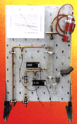
During the project ZEBA has developed a demonstration
model for condensing boiler technology (see graphic below). The demonstration
model can be used in practice-oriented initial and continuing vocational training.
With it students can easier understand the function of condensing boiler systems.
Also, frequently occurring errors can be simulated and test measurements be
performed. On the following pages the model and its function will be briefly
presented.
Graphic: Demonstration model - condensing boiler technology

14.1 Components
14.2 Structure
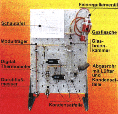
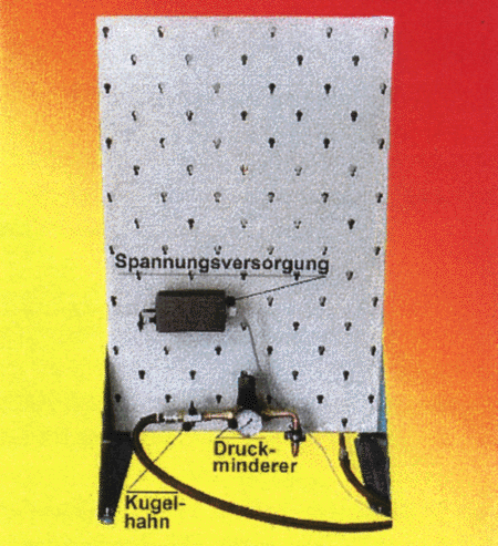
The model is delivered ready for operation. The following
two graphics show the model components and their arrangement.
Graphic: Condensing boiler model - Front view

| Schautafel | = | Diagram |
| Feinregulierventil | = | Fine flow control valve |
| Gasflasche | = | Gas bottle |
| Modulträger | = | Module rack |
| Glasbrennkammer | = | Glass combustion chamber |
| Digitalthermometer | = | Digital thermometer |
| Durchflußmesser | = | Flow meter |
| Abgasrohr mit Lüfter und Kondensatfalle | = | Exhaust gas pipe with fan and condensate trap/collector |
| Kondensatfalle | = | Condensate trap/collector |
Graphic: Condensing boiler model - Rear view

English translation of technical terms and sentences of the diagram above:
| Spannungsversorgung | = | Voltage supply |
| Druckminderer | = | Pressure-reducing valve |
| Kugelhahn | = | Ball cock/tap |